How Does Substation Remote Temperature Monitoring Work?
Select the interface by system responsibility
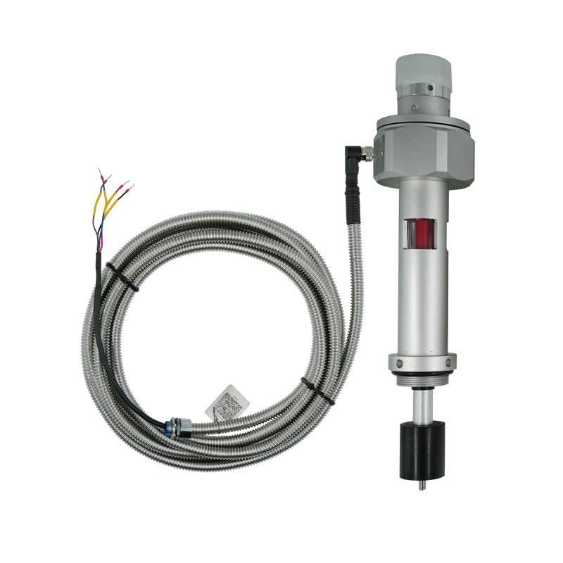
A Pt100 signal leaves excitation and linearization to the receiving instrument. It is familiar but sensitive to wiring method and lead resistance. A 4-20 mA transmitter provides a conditioned current loop that is often easier to supervise over distance. RS485 carries digital values but requires a documented protocol and network configuration.
The field instrument, remote display and control system must be specified together. State the input type, scale, supply, isolation, cable and terminal responsibility for every interface.
Keep measurement identity intact
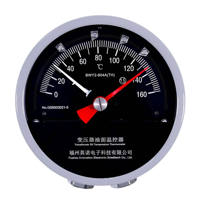
The remote tag should say whether the value is transformer top oil, simulated winding temperature or another measurement. Generic tags such as transformer temperature can lead operators to compare unlike quantities.
Use the same engineering unit and scale at the field instrument, transmitter and supervisory display. If a transmitter maps 0-160°C to 4-20 mA, that exact mapping belongs in the loop diagram and database.
Engineer reliable wiring and communications
Pt100 circuits need the correct two, three or four-wire arrangement supported by the equipment. Current loops need verified polarity, loop supply and total resistance. RS485 needs topology, termination, shielding, address and register-map control.
Route instrumentation wiring away from high-current conductors where practical and follow site grounding practice. A shield connected inconsistently at several points can create avoidable interference paths.
Commission end to end
Apply or simulate representative values and compare local indication with the panel and supervisory display. Verify alarm scaling, trend labels and loss-of-signal behavior.
Store the final scale, model, terminal diagram, communication settings and test results. Remote monitoring remains maintainable when a future technician can reproduce the complete signal chain.