Simulated winding temperature based on top-oil temperature and load-current heating
Shows the load-related thermal value used for transformer cooling and protection decisions.

Winding Temperature Indicators manufacturer and supplier
A mechanical WTI gauge and compound transmitter for simulated winding temperature indication on oil-immersed transformers, with adjustable contacts and remote signal options.
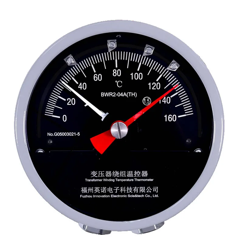
See how this model supports temperature indication, control contacts and remote monitoring.
Shows the load-related thermal value used for transformer cooling and protection decisions.
Assign the contacts to fan or pump stages, high-temperature alarm and trip logic as required by the transformer design.
Send the indicated winding temperature to a compatible panel meter, PLC or SCADA input.
Use these values to compare models. Request the latest datasheet and drawing for the exact suffix you plan to order.
| Operating ambient | -40°C to +65°C |
|---|---|
| Relative humidity | Up to 95% at 25°C |
| Measuring range | 0°C to 160°C |
| Accuracy | Class 1.5; stated maximum error ±2.4°C |
| Switch contacts | 4 adjustable contacts |
| Switch rated power | AC 220 V / 5 A |
| Remote signal options | Pt100; 4-20 mA by selected configuration |
| Capillary length | Defined by the final model code and project layout |
| Protection grade | IP55 |
| Common models | BWR2-06AJ(TH), BWR2-05J(TH), BWR2-04AJ(TH), BWR2-04J(TH) |
The BWR2 is a winding temperature indicator, often abbreviated WTI, for oil-immersed transformers. It does not place an electrical sensor directly inside the conductor. The system combines the measured top-oil temperature with a load-current-related heating effect in a compound transmitter. The pointer therefore represents a simulated winding temperature that can support operating decisions, cooling control and protection logic.
This product family is used when the project needs a durable local dial, adjustable switching contacts and an output for remote indication. Several model suffixes define the contact arrangement, signal method and environmental configuration. A replacement order should never rely on the BWR2 family name alone. The complete model, current-transformer input, existing pocket arrangement and wiring must be compared.
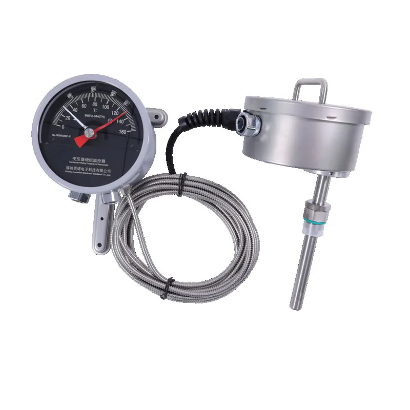
The temperature bulb responds to the transformer top-oil temperature. A current signal proportional to transformer loading is supplied from a current transformer to the compound transmitter. Its heating element adds a calibrated thermal rise to the sensing system. With no load, the indicated value follows top-oil temperature. Under load, the added rise moves the indication toward the calculated winding temperature.
The adjustable contacts can be assigned to cooling stages, alarm or trip functions according to the transformer protection design. Contact set points belong to the project commissioning record. They should be coordinated with the transformer thermal design, cooling stages and upstream protection scheme rather than copied from an unrelated installation.
Provide the complete existing BWR2 model code, number and purpose of switch contacts, required signal output, CT secondary current, capillary length, remote display requirement and environmental conditions.
Confirm whether the order is for a new transformer or a retrofit. A retrofit also requires the existing mounting dimensions, thermometer pocket, bulb arrangement, cable entries and terminal diagram.
Install the indicator vertically where the dial can be read and serviced. Protect the capillary from crushing, sharp bends and vibration. Insert the sensing bulb into the specified compound transmitter and thermometer pocket arrangement, then secure the route at suitable intervals.
Before energization, verify the contact continuity, terminal mapping, current-transformer circuit and remote output against the model-specific diagram. Functional testing should confirm local indication, each cooling or alarm stage and the receiving panel signal.
Review other models for the same transformer temperature measurement and control function.
Compare winding temperature indicatorsReview how OTI and WTI contacts support transformer cooling stages and protection logic.
Transformer cooling and protection applicationCompare existing codes, outputs, capillary routing and mounting interfaces before a controller replacement.
Transformer OTI and WTI replacement guideCheck available management-system, conformity and qualification materials for procurement review.
Certification and qualification documentsSales and engineering support
Tell us the transformer type, required temperature range, contact functions, output signal, capillary length, quantity and destination. We will help you identify a suitable model and send the available technical documents.