0-100°C or 0-120°C measuring ranges
Select the range that matches the transformer top-oil limits and existing control scheme.

Oil Temperature Indicators manufacturer and supplier
A transformer top-oil temperature controller with local indication, Pt100 remote signal and adjustable control contacts.
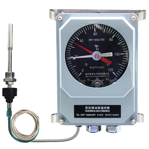
See how this model supports temperature indication, control contacts and remote monitoring.
Select the range that matches the transformer top-oil limits and existing control scheme.
Send a resistance temperature signal to a compatible remote display or signal converter.
Supports outdoor installation and local switching for cooling or alarm circuits.
Use these values to compare models. Request the latest datasheet and drawing for the exact suffix you plan to order.
| Output signal | Pt100 resistance signal |
|---|---|
| Measuring ranges | 0-100°C or 0-120°C |
| Accuracy | Class 1.5; stated maximum error ±1.8°C for 0-120°C |
| Switching error | ±2°C |
| Switch rating | AC 220 V / 3 A; DC 220 V / 1.5 A |
| Operating ambient | -40°C to +55°C; humidity up to 95% |
| Protection grade | IP55 |
| Temperature bulb | Φ14 mm; insertion depth at least 150 mm |
| Mounting thread | M27 × 2 mm |
| Standard capillary | 5 m |
| Optional remote conversion | 0-5 V, 4-20 mA or RS485 through a compatible display |
The BWY-802 and BWY-803 controllers measure transformer top-oil temperature and provide a Pt100 resistance signal for remote indication. The mechanical pointer and adjustable contacts support local operating checks and cooling control.
A compatible digital display can convert or retransmit the Pt100 signal as a voltage, current or RS485 interface. The final remote architecture should define who supplies excitation, how cable resistance is handled, and where signal conversion occurs.
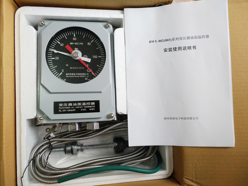
The bulb, capillary and mechanical sensing element form a sealed temperature system. Oil temperature changes move the pointer and the adjustable microswitch mechanism.
The composite sensing arrangement also provides a Pt100 output. This allows the control room to display the temperature without relying on visual inspection of the local dial.
Choose the 0-100°C or 0-120°C range, confirm contact rating and use, Pt100 wiring, capillary length, mounting dimensions and any remote conversion requirement.
For a BWY replacement, send photographs of the nameplate and terminals together with the existing installation drawing.
Insert the bulb into the designated top-oil pocket with the required insertion depth. Do not shorten, kink or sharply bend the capillary.
Verify Pt100 loop resistance and receiving-instrument configuration. Test every switch point using the approved commissioning method.
Review other models for the same transformer temperature measurement and control function.
Compare oil temperature indicatorsReview how OTI and WTI contacts support transformer cooling stages and protection logic.
Transformer cooling and protection applicationCompare existing codes, outputs, capillary routing and mounting interfaces before a controller replacement.
Transformer OTI and WTI replacement guideCheck available management-system, conformity and qualification materials for procurement review.
Certification and qualification documentsSales and engineering support
Tell us the transformer type, required temperature range, contact functions, output signal, capillary length, quantity and destination. We will help you identify a suitable model and send the available technical documents.