How Does Distribution Transformer Temperature Monitoring Work?
Start with the operating and maintenance model
A transformer inspected regularly may only need a robust local oil temperature indicator and a high-temperature contact. An unattended compact substation may benefit from remote temperature, level and pressure data. The project should identify who observes the value and what action follows an abnormal condition.
Remote data is useful only when the receiving terminal maps the register, scales the value, timestamps the event and routes an alarm to a responsible operator. Hardware selection should therefore include the monitoring platform rather than stop at the sensor output.
Compare mechanical and powered monitoring
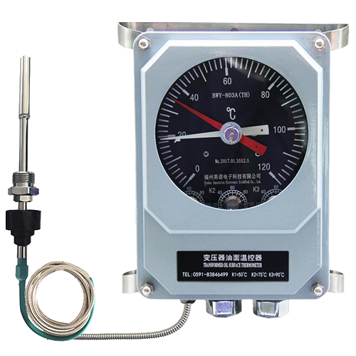
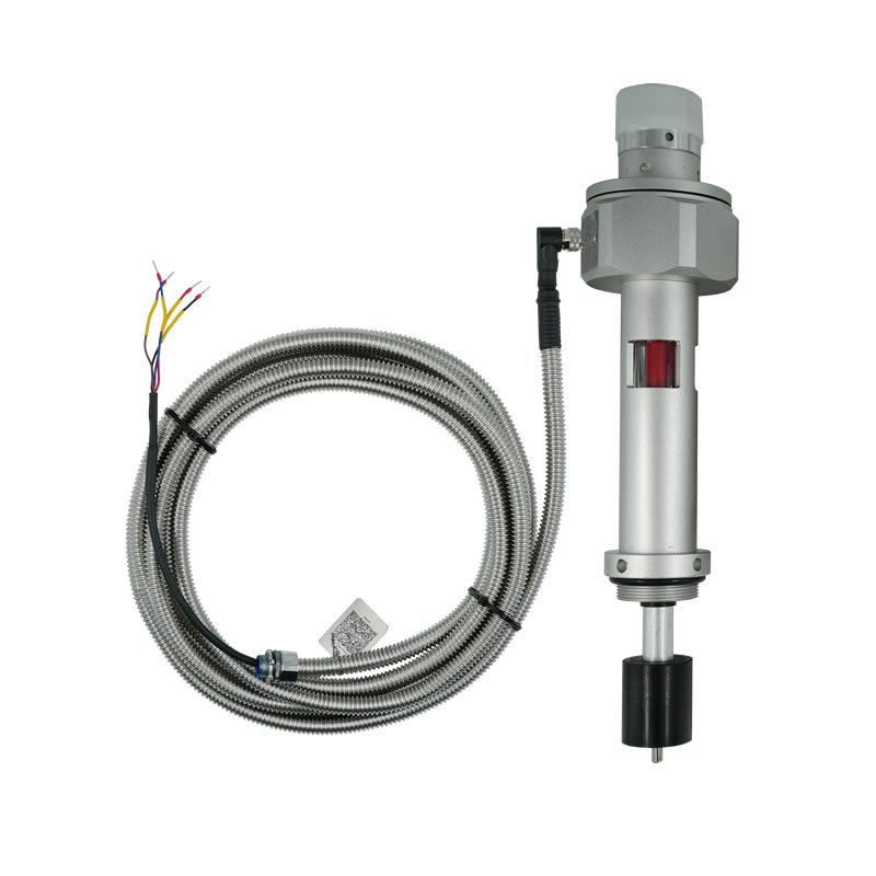
Mechanical BWY instruments can indicate top-oil temperature without an external electronic supply. Adjustable contacts can start cooling or raise an alarm. A powered multi-parameter device requires DC supply and communications but can consolidate several transformer condition values.
The choice is not simply old versus new technology. Mechanical instruments offer direct local visibility and simple control. Digital monitoring offers remote fleet awareness. Some projects use both to preserve local indication while adding supervisory data.
Confirm the mounting arrangement
Distribution transformer tanks and compact substations have limited space. Check the existing gauge opening, thread, insertion depth, float movement, cable route and maintenance clearance. The sealing system must be compatible with transformer oil and the enclosure rating required by the site.
If an integrated oil-level device replaces a traditional gauge, verify that the level geometry corresponds to the tank and normal oil expansion range. Installation drawings should control the decision.
Plan commissioning and lifecycle support
Test the local display or digital values against the commissioning method, then verify alarm thresholds at the receiving terminal. Record the communication address, register map, scale and power circuit.
Fleet deployments should standardize the model code, cable assembly and configuration record. Spare units and replacement procedures are easier to manage when each site uses a controlled selection sheet.